Tuning bump steer and bump steer linearity

Bump steer (or Roll steer) is a measure of wheel steer angle change with vertical suspension travel.  Bump steer is a common tuning lever used in vehicle dynamics.  In most cases it is tuned to give an understeer tendency on a suspension system (i.e. toe out on a front axle and toe in on the rear axle), but there can be exceptions to this. 

In the design of any suspension system, it is wise to include the option for some bump steer adjustment.  There are two main reasons for this.  The first is to correct for any build tolerance during the suspension manufacture.  The second is to fine tune the handling of the vehicle using an easily accessible tuner even after the vehicle is fully built and on the road. 

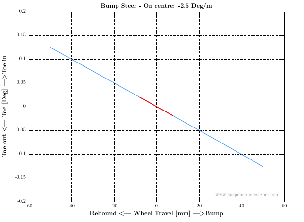
The second aspect to bump steer which can be overlooked is bump steer linearity.  Linearity refers to the shape of a bump steer curve.  In most cases it is desirable to have linear bump steer to give linear handling response on a vehicle with different levels of roll (toe angle change vs wheel travel is a straight line).  Linearity will be explored as part of this tuning example.

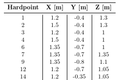
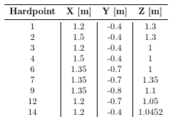
Bump steer is tuned on a suspension system by the positioning and length of the track rod relative to the other links in a suspension.  In this example, a relatively simple double wishbone layout is simulated using RACE to explore the influence of the track rod position and length on bump steer.  The goal is to design a suspension system with -2.5 Deg/m bump steer.

The layout of this example is shown above.  The Lower Control Arm (LCA) is parallel to the ground plane and is 300mm long.  The Upper Control Arm (UCA) has the same link end y-coordinates and is slightly inclined as shown above.  The track rod is initially positioned 50mm above the LCA and is 350mm long.  The full set of 3D suspension hardpoints is given at the bottom of this post.  The baseline bump steer curve for this design is shown below.

Examining the curve above, the on-centre bump steer is -8.4 Deg/m (‘on-centre’ means around the suspensions normal ride height, i.e. around 0mm wheel travel) .  This is above the target value of -2.5 Deg/m and therefore needs to be tuned by changing the suspension hardpoints. 

As with any suspension tuning scenario, the designer now has a choice of which hardpoint or hardpoints to change.  For a given suspension characteristic, some hardpoints are more sensitive than others.  With experience the designer builds up knowledge of which hardpoints affect which characteristics and can therefore quickly identify the best hardpoint to change.  In this scenario, bump steer is very sensitive to the z position of the toe link and the toe link inclination in front view.  So the focus will be on tuning the inner track rod ball joint z height to get bump steer back to the target value.  Something to be aware of with hardpoint changes is that they can affect more than one suspension Key Performance Indicator (KPI) at a time.  So if you focus on tuning one KPI and ignore all others, you may end up changing a lot more than you intended.  This interconnection of KPIs will be explored in a future post.

So after a few iterations, the inner track rod ball joint was moved down in z by 5.6mm.  The updated bump steer curve is shown below.

The on-centre bump steer is now at the target value of -2.5 Deg/m.  Although the target value has been delivered on-centre, off-centre the curve is very nonlinear.  Although not shown here, RACE reports bump steer at 25mm bump and 25mm rebound as a measure of the linearity of the curve.  In this case at 25 mm bump the bump steer value is -6.7 Deg/m and at 25mm rebound +1.7 Deg/m.  From a handling point of view, this will give nonlinear steer behaviour in roll.  In most cases this is not desirable.

To correct the non-linearity highlighted above, the focus needs to turn to the track rod length relative to he other links in the suspension system.  Note that the baseline model was built with a track rod which was 50mm longer than the LCA (this was intended to demonstrate the impact on bump steer linearity).  Notice the C-Shape of the curve above, this is a hallmark of a track rod which is too short or long.  In this case it is too long and needs to be shortened.  To shorten the track rod without changing the on-centre bump steer it needs to be shortened along a line joining the track rod outer ball joint and the track rod inner ball joint.  The result of this change is shown below (the track rod is now ~300mm long).

The linearity of the curve is significantly improved compared to the previous result.  The bump steer at 25mm bump, on-centre and 25mm rebound are all-2.5 Deg/m.

As mentioned earlier, it is useful to design some bump steer adjustment into a suspension system to allow tuning once the vehicle is complete.  As demonstrated here the z position of the track rod inner or outer ball joints are very sensitive for tuning bump steer.  The method used in this example is equivalent adding or removing shims under the steering rack mounting.  The advantage of tuning the linearity of the curve is that this linearity is unaffected if the z height of the rack is changed.  This is demonstrated below with a 5.6mm upward rack movement.

Note that this reverses the downward rack move we did earlier in the tuning loop.  This takes the bump steer back to the baseline value of -8.4 Deg/m but in this case now that the track rod length has been optimised, the bump steer linearity is maintained.

The suspension hardpoints used for the baseline (left) and -2.5 Deg/m linear bumpsteer example (right) are shown below.  The hardpoint numbers follow a common convention used in the automotive industry.  1 and 2 are the UCA inner hardpoints, 7 is the UCA ball joint.  3 and 4 are the LCA inner hardpoints and 6 is the LCA ball joint.  9 is the wheel centre.  12 and 14 are the track rod outer and inner ball joints , respectively.

In summary, this post gives an idea of the process and approach to bump steer tuning on a suspension system.  The example was intentionally kept simple and a basic double wishbone suspension layout was used to demonstrate the tuning principles. 

This is the first in a series of tuning articles on suspensiondesigner.com, more will follow.   The graphs were taken directly from the RACE pdf report for each simulation scenario.  The key goal of RACE software (RApid Concept Evolution) is to allow a suspension designers to quickly carry out tuning such as this without the need to build complex multibody simulations or learn any new software packages.  If there is a particular suspension tuning guide or scenario that you would like explored using RACE, please get in touch via twitter or by email on the contact page.


Related posts: Bump/Roll Steer


Back to suspension design library index